R-Zone was a head-mounted game system from Tiger Electronics in 1995.
Ranger_Lannier sent me several cartridges to dump. I was unable to find the cartridge pinout on the web, so I opened several carts, the head unit and the hand controller.
Like Microvision, R-Zone carts contain the microcontroller, but they also house the LCD panel specific to the game, and some have an additional ROM. The MCU is covered with an epoxy glob. Indy 500 uses a Sharp SM510, but games can use different MCUs.
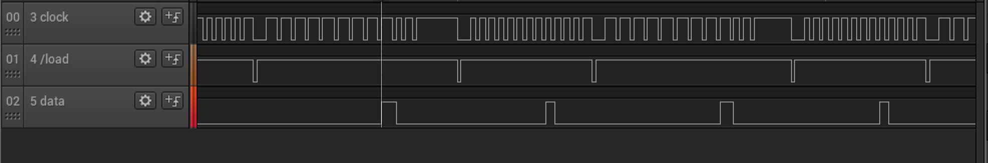
The head unit just has the cart connector, 4 LEDs for backlight and a speaker. The controller has 14 buttons, 2 potentiometers (volume and brightness), a cap, a resistor, battery holder and a blob. The blob holds a couple of 74HC165 shift registers that take the buttons as parallel inputs and send them to the cart as serial data, much like the Nintendo controllers. The cable from the controller to the head unit has 7 wires: +3V, ground, brightness, volume, and the controller data - clock, data and /load. The patent says that the clock line is connected to the SM510's S1 output, /load goes to S8, data goes to K3, and the BS segment output goes to the backlight LEDs, but the unit I have is different. It's a little difficult to tell because the traces were under the epoxy blob and I used Dynaloy Decap to clean the die and it did a number on the PCB. But it looks to me like the clock line is on S2 and the backlight LEDs are on S1. The K1 input was used for data, and it looks like R2 was used for /load. The clock line is repeatedly toggled 13 times by the cart after pulsing /load low. The buttons are each assigned one clock - if a button is pressed, the blob sets the data line high for the corresponding clock bit. /load going low loads the buttons into the shift register and outputs the ON button state. The other buttons' states are output at the rising edge of each clock: UP, RIGHT, LEFT, DOWN, A, B, C, D, SOUND, SELECT, OFF, PAUSE and START. Even when the unit is turned off, the /load line is still pulsed at about once per second to check to see if you hit the ON button. Here's a picture of the signals when the SOUND button is pressed.
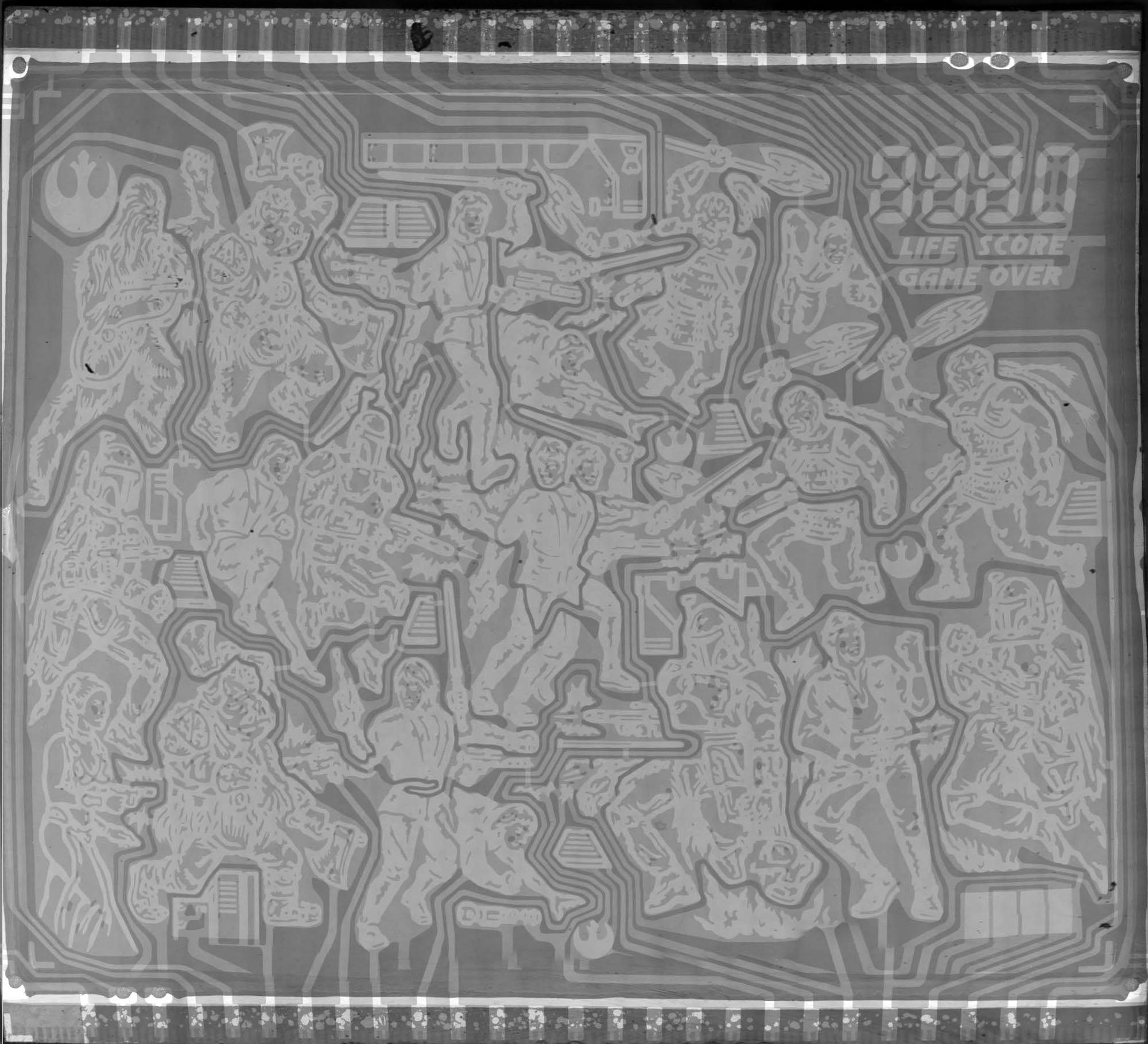
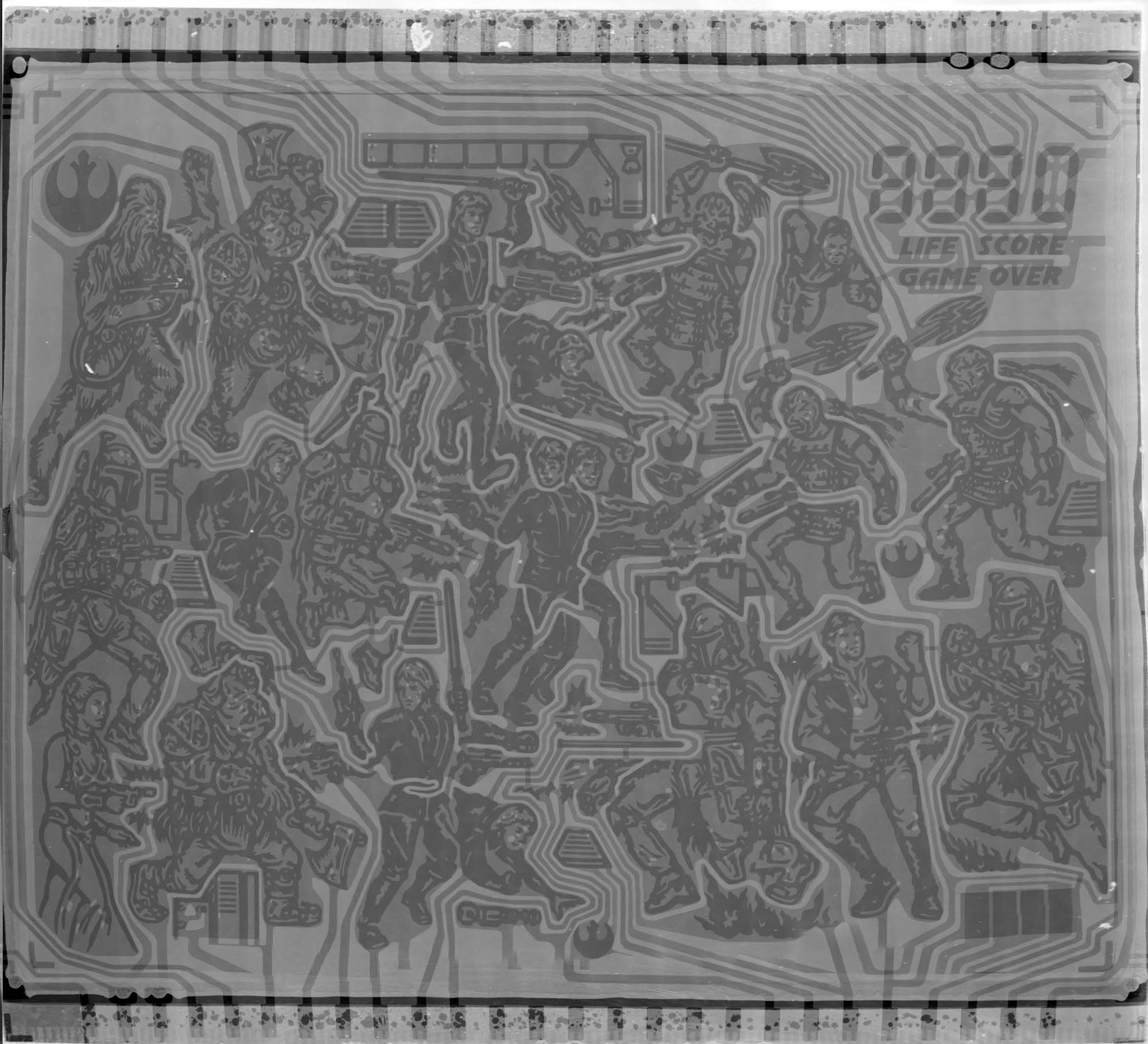
I can't see anything on the cart's LCD looking at it naked eye, but I played with lighting and focus on the microscope and was able to see the segments. I took pics of the LCD screen from the cart Jedi Adventure. Here's the same pic with B&W inverted. I just threw the pics into Microsoft ICE to composite, but it didn't align the tiles correctly, so I had to adjust it in Photoshop. That's why the geometry looks weird, so later I will composite the pics better. You can see pads on the upper and lower edges that connect to each segment. Here's a pic of the LCD with all segments turned on.
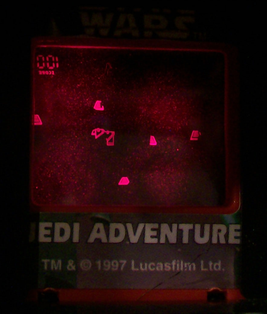
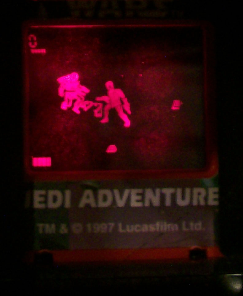
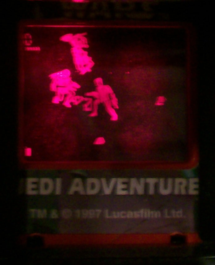
I also took some pictures 1 2 3 of the head unit with Jedi running. The images are backwards because you are supposed to look at the reflection in the eyepiece, not directly at the LCD screen. You can see where the 4 LEDs are located - they should have used more, smaller LEDs or a better diffuser.
Here's the R-Zone patent, showing parts and net list. The net list doesn't match the unit that I have. There are also a couple of design patents for the headgear and the later handheld package.
Paul has a web site with lots of SM510 info, an assembler, and an emulator for the Watchman.